
Solving yesterday's problems today
© 1999-2023 Jürgen Müller
juergen@e-basteln.de
Solving yesterday's problems today
© 1999-2023 Jürgen Müller
juergen@e-basteln.de
Atari’s original PONG arcade game has an interesting design: No microprocessor or program; the whole game logic and signal generation are hard-wired from sixty-some TTL chips. So, when I got my hands on an original 1972 PONG circuit board, I wanted to build a playable cabinet around it, but also display the board with its surprisingly low-integration components.
I decided to take my half-scale Asteroids idea a step further, and give center stage to the circuit board in a cabinet styled like a picture frame. The shallow depth of the frame (6 cm, a good 2") means that there is no room for a period-correct cathode ray tube; an 8" TFT is used instead. But I added a homebrew, FPGA-based video upscaler to simulate scan lines, horizontal blur and some phosphor afterglow, which makes the image look “right” to my eyes.
While this project is complete and has turned out nicely, this web page is preliminary. Just a few pictures for now, to give you an idea, and some relevant links and project files.
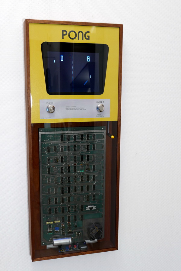
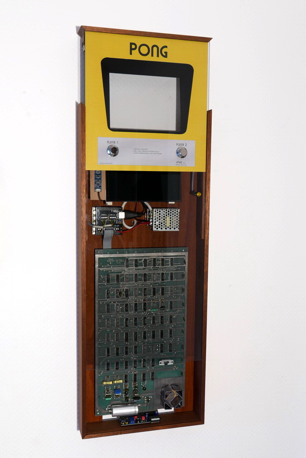
The finished PONG cabinet. Wall-mounted, with mains power supplied via a wall outlet behind the frame. The cabinet is 74 cm tall, 29 cm wide, and 6 cm deep.
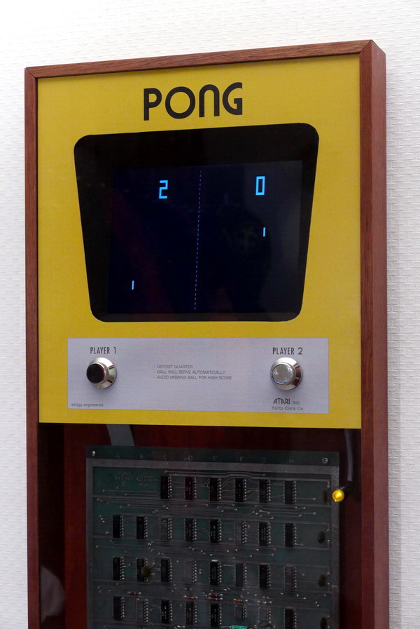
The complete front panel and circuit board are covered by a pane of slightly tinted perspex. The yellow front and the 'aluminum' panel are simply laser-printed. The two paddle knobs and a coin button are real, of course.
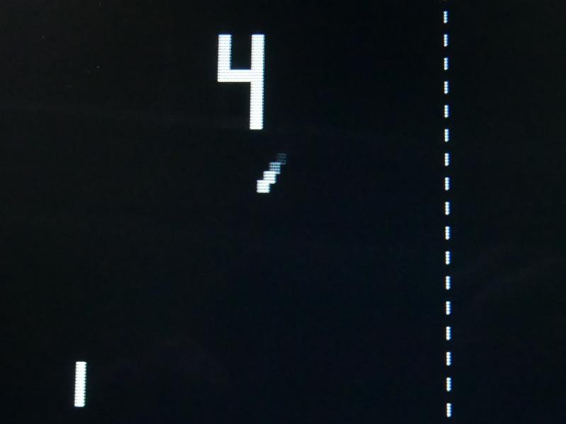
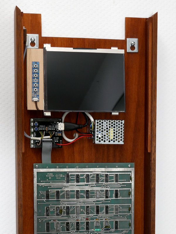
An 8" TFT flat screen is used, but the FPGA video upscaler adds scan lines, phosphor afterglow and a bit of horizontal blur, to get close to the looks of the original cathode ray tube.
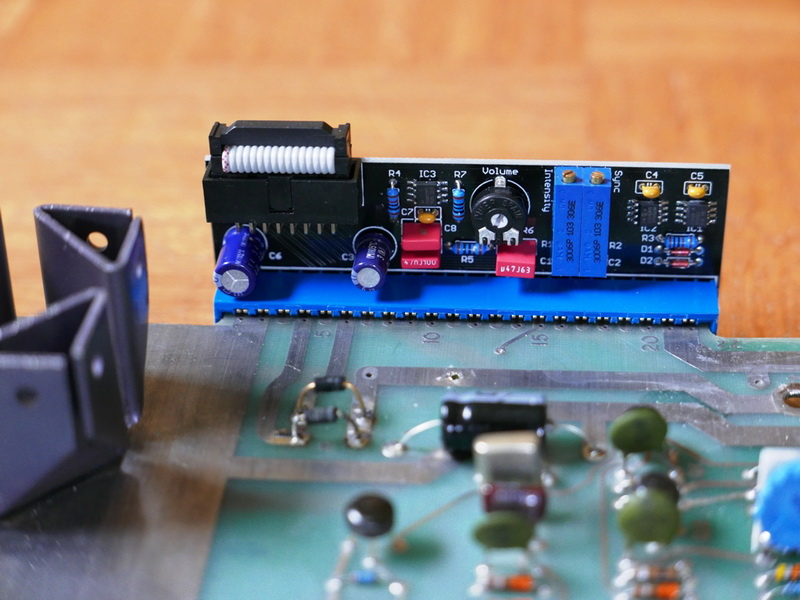
A small interface board sits directly on the PONG board's edge connector. It amplifies the sound, splits the video output into a sync and a brightness signal for the upscaler, and feeds a regulated +5V supply to the PONG board. PONG's on-board voltage regulator is bypassed, to improve reliability and reduce the heat load in the cabinet.
The whole front slides up to give access to the innards, for installation and service. The FPGA video upscaler and 5V power supply sit below the screen. The speaker and controls are attached to the front panel. They get connected via a Sub-D jack in the upper left that clicks into place when the front is lowered all the way.
The TFT screen is set back and tilted backwards a bit, reminiscent of the original PONG cabinet. The opening on top provides ventilation and an outlet for the speaker sound. To allow air circulation, the whole frame sits away from the wall on 1 cm spacers, and there is another ventilation opening at the bottom of the back panel.
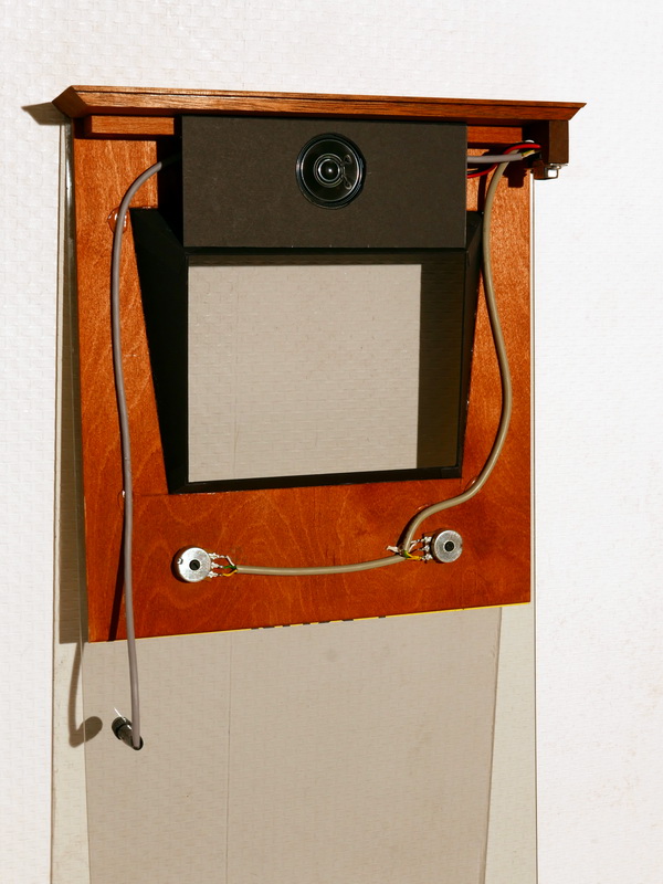
The backside of the front panel. The little speaker is mounted here, behind a baffle which helps to get a bit of low end. The baffle and the trapezoidal screen bezel were cut from 1.5 mm cardboard. The Sub-D jack which connects the paddles, coin button, and speaker via its counterpart in the frame is visible in the upper right.