
Solving yesterday's problems today
© 1999-2023 Jürgen Müller
juergen@e-basteln.de
Solving yesterday's problems today
© 1999-2023 Jürgen Müller
juergen@e-basteln.de
Editor’s note, August 2018: These instructions were written a long time ago. DanElectro has discontinued the Dan Echo, and their current product lineup looks dubious to me. But it is still worthwhile to buy a used Dan Echo if you can find one! – I have not updated the text below. The various semi-professional conversions are no longer offered. But components for the DIY modification are now easier to find; e.g. Mouser, DigiKey, and Conrad all carry the TLV2460CD op amp as well as suitable resistors.
The Dan Echo is a digital echo/delay effect pedal made by DanElectro. It’s priced reasonably, comes in a very sturdy housing, is easy to use and hence popular with many musicians – including harp (that’s harmonica) players. Unfortunately, many harp players complain that the DanEcho “sucks the tone” from their playing. Specifically, the low-frequency “bottom end” is often weakened or lost when running the microphone through the DanEcho.
This page describes how to optimize your DanEcho for use with high-impedance microphones, especially crystal or ceramic mics, as used by many blues harp players. It describes a simple modification to the DanEcho’s internal circuit board, using parts for about $3. Some soldering skills are required; of course, this modification will void your DanEcho’s warranty. Alternatively, the last section will describe how to build an external buffer amplifier for using high-impedance microphones with any effect pedal.
The small print: This modification will void your DanEcho’s warranty. Neither DanElectro nor myself will be responsible for any damages to the DanEcho or any connected equipment resulting from this modification. On the positive side, there are no dangerous voltages inside the DanEcho which could present hazards during your work! – If you have any suggestions or questions, please send an email to juergen@e-basteln.de – thanks!
(C) 2002 Jürgen Müller, juergen[at]e-basteln.de
The input impedance of the DanEcho is much lower than the 1 MOhm typically found in tube amps – only about 100 kOhm for the DanEcho. Crystal and ceramic mics are especially sensitive to such a lower-impedance load; they will lose a lot of the low frequency part of their output. Dynamic microphones (including the older controlled reluctance types etc.) are not as sensitive to lower impedances. This would explain why users of dynamic mics, like the Green Bullet, may be happier with their DanEcho than JT-30 users.
The modification desrcibed here adds a little buffer amplifier to the input, which provides an input impedance of 1 MOhm or higher. It sits directly on the DanEcho circuit board, works from the pedal’s standard internal power supply, and sounds fine to me.
If you don’t like the idea of approaching your DanEcho pedal with a soldering iron, there are two outfits who will carry out a similar modification for you. Ron Holmes charges $75 for the mod, John Kinder asks $140. I assume they use the same approach as presented here, but since I have never seen a pedal modified by either Ron or John, that’s just an educated guess. If you are handy with a soldering iron (or know someone who is), I would definitely recommend the do-it-yourself modification…
Mike Curtis has instructions for building his MikeMojo, or will build you one for $50. It’s a buffer amplifier like the one presented here, but is intended to be mounted in a separate box outside the DanEcho. Hence, it can be used with other effects or amplifiers as well, but requires additional housing and connector hardware, and will need its own power supply (two extra 9V batteries for the dual supply voltages it requires). If you would prefer a separate unit, please also check the section “Building an external unit” below, which shows how to modify the single-supply design presented here for installation in a separate box.
By the way – the DanEcho has an additional quirk: Its electronics remain in the signal path even when the DanEcho is in “bypass” mode. Pushing the bypass button does not create a direct connection between the input and output jacks. Instead, the signal still goes through the DanEcho circuit – including the low-impedance input section –, just the echo effect is switched off. Hence the complaints that the DanEcho affects tone even when switched off. I am not aware of a modification which converts the DanEcho to “true bypass”. Since the pedal sounds good after the modification, even in “dry” mode with the echo switched off, I don’t think there’s a need to go further.
If you are technically minded and want to look at the actual circuit change, here’s the diagram of the DanEcho’s input stage before and after the modification. (If this does not mean anything to you, I hope you can still safely make the modification by following the instructions below.) When comparing the diagram with the instructions below, please note that the circuit is on two different boards, as indicated by the dashed line.
Circuit diagram before and after the modification
The original input stage has a simple transistor input buffer. With the transistor itself, the 220 kOhm pull-up resistor and the 470 kOhm input termination, the overall input impedance is just about 100 kOhm at audio frequencies. The modification replaces the transistor with a unity-gain operational amplifier. This amplifier’s very high-impedance input allows us to move to higher-impedance resistors as well. With resistor values of 2 to 3 MOhm each, an overall input impedance of 1 to 1.5 MOhm is obtained – as also found in typical tube guitar amplifiers.
It is important to chose an op-amp which works well with the limited 5V supply voltage available inside the DanEcho: There is not much headroom between the supply range and the signal amplitude, so the op-amp’s input and output must be capable to swing over the full supply voltage range (this is called “rail-to-rail operation”). I used a TLV2460 from Texas Instruments. It is especially suited for battery-powered operation, because it offers single-supply voltage, rail-to-rail-operation, and low power consumption. It also has quite good noise characteristics. I don’t use the TLV2460’s shutdown mode, so the TLV2461 is an equivalent choice at a lower price. See the data sheet from Texas Instruments for details.
1 operational amplifier, TLV2460, TLV2461 or similar. I used the small-outline package, TLV2460CD. Due to its small size, it can be soldered directly to the terminals of the transistor it replaces. But it’s a bit of a fumble to solder, and there is enough space to mount the standard dual-inline package, TLV2460CP. The TLV2461 should be an even better choice, with exactly the same performance and a lower price (due to its lack of a shutdown mode, which is unused here anyway) – this just was not available when I ordered. If you are into electronics, it’s of course possible to substitute a different op-amp type. The required characteristics are pointed out in the Circuit section just above.
2 metal-film resistors, 2 to 3 MOhm. (That’s MegaOhm, 106 Ohm.) Exact values are not critical. I used 3 MOhm; 2 MOhm may be easier to obtain and should also work fine, resulting in 1 MOhm overall input impedance. Standard 1/4 Watt resistors will be fine; other sizes are also suited. Metal-film is recommended over carbon film (cheaper and more widely available), since it will exhibit lower noise. However, I have not tried carbon film resistors in this application, so they may work.
A few inches of fine, single-stranded, isolated wire. 30 AWG (0.25 mm core diameter) works well for me.
Unfortunately, both the TLV246x, or similar single-supply op-amps, and the MegaOhm metal film resistors, are not-so-common components which are probably not available at your local electronics store. The components are available from online sources on the web; some examples are given below. However, it may be difficult to find a single source carrying both items. In the US, you might order from Digi-Key and go with 2 MOhm resistors; being based in Germany, I ended up ordering from two different suppliers (RS components and Conrad).
Digi-Key is a large, US-based distributor. There part no. for the TLV2460CD is 296-2432-5-ND, for the TLV2460CP it’s 296-7480-5-ND (both $1.40 at the time of writing). Metal film resistors are available in small quantities (5) up to 2 MOhm, part no. BC2.00MXCT-ND. Larger resistor values are apparently available in minimum quantities of 5000, only.
RS Components is represented in many countries (but not in the US). If they do not have a branch in your country, they can export from the UK. They carry the small-outline TLV2460CD (no. 356-8161), the dual-inline TLV2460CP (356-8177) and the corresponding 2461 types. Metal film resistors are only available up to 1 MOhm, unfortunately. You could always use two or three of these in series … I looked up the op-amps in the German catalog and checked the UK catalog as well. The part numbers appear to be the same for the various national branches, but please check!
Conrad Electronic is a popular distributor in Germany. They have 3 MOhm metal film resistors (part no. 420328), but I could not find a suitable op-amp.
Only standard hand tools are required. You should be reasonably proficient with the soldering iron, especially when using a small-outline op-amp package.
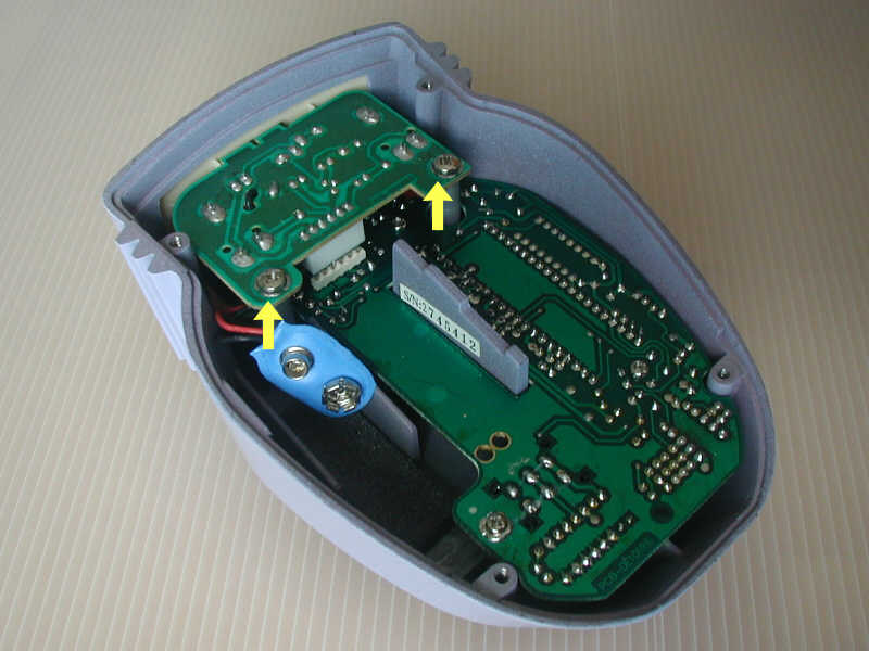
Remove these screws to detach the connector PCB.
Please compare the PCB revision numbers with the ones these instructions refer to.
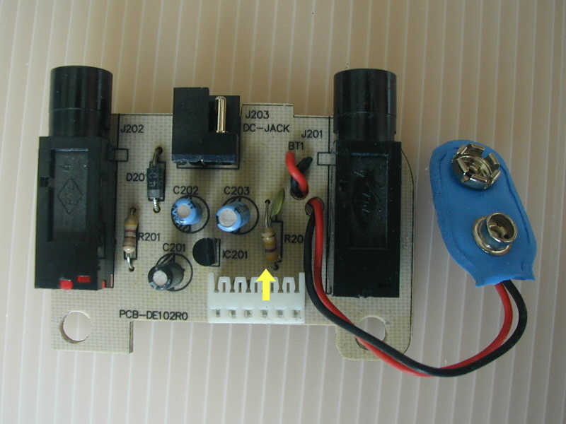
On the connector board, locate resistor R204 (see arrow). Unsolder, and replace with 3 MOhm resistor. (In my DanEcho, DanElectro had added a small capacitor, probably 10 pF, in parallel with R204. If I’m correct about its value, it does not do anything to the audio signal, but rather seems to prevent the DanEcho from receiving AM radio or such. Hence, I put it back in place after exchanging the resistor.)
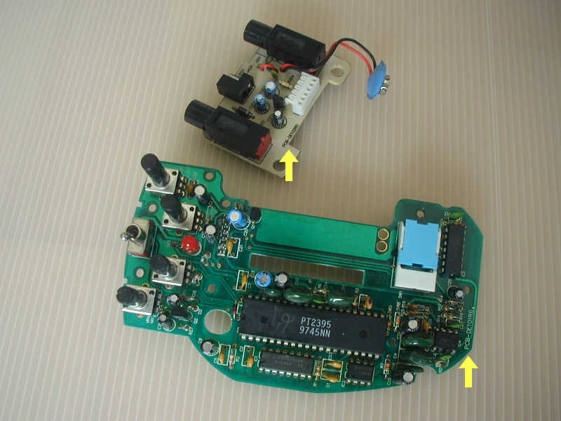
On the main board, locate resistor R11 (see arrow). Unsolder, and replace with 3 MOhm resistor.
On the main board, locate and unsolder transistor Q1 (see arrow). This will be replaced by the new operational amplifier in the final steps.
On the main board, locate and unsolder resistor R13 (next to Q1). This is not used anymore and will not be replaced. – Note: As can be seen in the photo, one lead of R10 has also been cut off, removing R10 from the circuit. This was done in the DanElectro factory, and is unrelated to the mod.
Replace R204 with a 3 MOhm resistor.
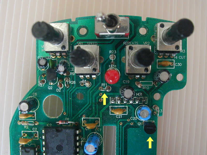
Replace R11 with a 3 MOhm resistor. Remove transistor Q1 and resistor R13.
Now mount the operational amplifier. When using the small-outline type, TLV2460CD, some of the legs can be directly soldered to the former Q1 terminals – see the photo and diagram below. You may still want to attach the body of the op-amp to the circuit board with a drop of superglue or hot glue. (I didn’t, so mine is held in place by the solder connections only. Not very good style, I am told…) When using the larger dual-inline package, I would prefer to flatten out all pins, glue the chip to the empty area of the circuit board next to Q1, and use wires for all the connections.
Connect wires according to the photo and the schematic drawing below. In the drawing, the black dot on the chip denotes pin 1 – there should be a recessed dot on the chip itself, too. 3 wires are required for a TLV2460CD (red lines), and 3 pins are soldered directly to the former Q1 terminals (red dots). Use extra wires to avoid the direct pin-to-terminal connections when mounting an op-amp in the larger dual-inline package.
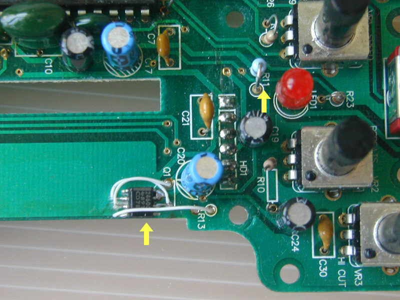
Mount the op amp which replaces Q1.
Connect the new op amp like this, with two direct connections to solder pads and three short wires.
Re-assemble the DanEcho in reverse order of disassembly:
On the other hand, while you have the DanEcho apart, you may consider re-painting it. (If you happen to dislike the violet/pink color, like I did.) The “V” ornament and the footswitch button are screw-mounted to the case and are easily removed; the plastic insert for the connectors and control panel is just inserted loosely anyway. The stripped metal case can then easily be sanded and painted. Mine now has a charcoal hammertone finish. No, I don’t feel this produced any further improvements in tone ;-)
Repainting the DanEcho does not change the tone much, but hey...
While I was looking at the DanEcho’s input circuit, I also checked the power supply section, which is located on the piggy-back connector board. Since I had not ordered DanElectro’s external power supply, I was wondering whether I could safely use a cheap, unregulated “wall wart” power supply instead, or whether the more expensive regulated type is required.
As can be seen from the circuit diagram below, the pedal itself includes a standard voltage regulator to create a stable 5V supply voltage for the pedal electronics. Hence, it is safe to use an unregulated supply, set to either 9V or 7.5V DC. (The regulator also confirms that it’s absolute nonsense to use DanElectro’s “vintage batteries”. Rest assured that the DanEcho’s electronics are well-isolated from any specific properties of the battery…)
The DanEcho's internal power supply circuit
By the way, my DanEcho draws just below 40 mA of current – pretty much independent of whether the echo effect is active or “bypassed”. The modification described here has not measurably changed the current consumption. With typical capacities of 500 to 600 mAh, an alkaline 9V battery should last 10 to 12 hours. Not great, but fair enough. I guess the reports of extremely short battery life, which occasionally show up on the web, are due to forgetting that the DanEcho is still powered when in bypass mode. (Since the LED indicator light is off, there’s no reminder that the DanEcho is still on and drawing current.)
As discussed in the first section of this page, there may be reasons for building an input buffer in a separate box, instead of incorporating it into the DanEcho – maybe you want to use your high-impedance microphone with a choice of different effects, or you just don’t have a DanEcho but some other echo effect, and are not familiar with its internal circuit.
The circuit diagram below shows how to adapt the circuit used for the DanEcho modification for mounting it separately. It’s the same single-supply op-amp buffer, but modified for operation from a separate 9V battery. A few changes from the internal version discussed above:
Circuit diagram for an external input buffer unit, powered from a 9V battery
You will have to use a different op-amp, since the TLV246x is only intended for supply voltages up to 6V. The TLV237x is very similar, but can stand the higher 9V supply voltage. (TLV2371 is preferred because it’s cheaper; TLV2370 has unnecessary shutdown input, but can be used as well if it should be easier to obtain.) The dual inline version is recommended for easier handling. The suppliers mentioned above should also carry this op-amp.
On the other hand, the somewhat larger supply voltage (9V instead of the regulated 5V inside the DanEcho) makes it acceptable to use a standard op-amp. The LM741, for example, is not a rail-to-rail operation type, i.e. the input and outputs will typically go from approx. 2V to 7V or somewhat less. This leaves a useable range of 4 to 5V; not much less than the DanEcho’s internal 5V supply range, and probably enough for most microphones and playing styles. Why not start with a simple standard op-amp that’s easily available – if you mount it in a socket, you can easily replace it later with a TLV2371 if you happen to overdrive it or are unhappy with the battery lifetime.
Two additional capacitors are needed. These can be Tantalum or any other electrolytic capacitors. Capacity should be 1 µF, voltage rating 16V or higher. Polarity is uncritical when mounting these. These should be readily available in any electronics store.
The resistors are the same as before, but used somewhat differently, in order to pull the input signal to half the supply voltage.
Of course, some additional hardware is required: Small enclosure, piece of circuit board, 9V battery clip, 1/4 inch jacks for input and output. Instead of the output jack, a short piece of audio cable with a 1/4 inch plug may also be convenient.
The circuit diagram shows a trick popular with effect box manufacturers for switching the battery power on whenever a microphone is plugged into the input jack: Use a stereo input jack, connect the battery’s ground (negative) terminal to the “ring” connection of the jack. When a mono 1/4" plug is inserted, both the “ring” and “sleeve” connectors of the jack will touch the sleeve of the plug; this connects the battery ground to the circuit main ground. – Of course, you can also install a separate switch in one of the battery connections.
The quiescent current of the op-amp is below 1 mA, resulting in about 800 hours of expected stand-by (silent) operation from one alkaline battery, and probably still several hundred hours of active use. So I guess battery operation is acceptable. I advise against installing a power indicator light/LED, because its power consumption easily exceeds that of the circuit. Just keep in mind to switch the unit off or pull the microphone plug after use…
I would appreciate any feedback on practical implementation and use of the stand-alone or integrated buffer version. Please send an email to juergen[at]]e-basteln.de – thanks!