
Solving yesterday's problems today
© 1999-2023 Jürgen Müller
juergen@e-basteln.de
Solving yesterday's problems today
© 1999-2023 Jürgen Müller
juergen@e-basteln.de
This little manual paper tape reader is easy to build and operate. It connects to any modern computer via USB, and performs well with all kinds of 5 to 8 bit paper tape, including translucent paper materials. To compensate for sensor tolerances and adjust to different paper types, it can automatically calibrate its optical sensors.
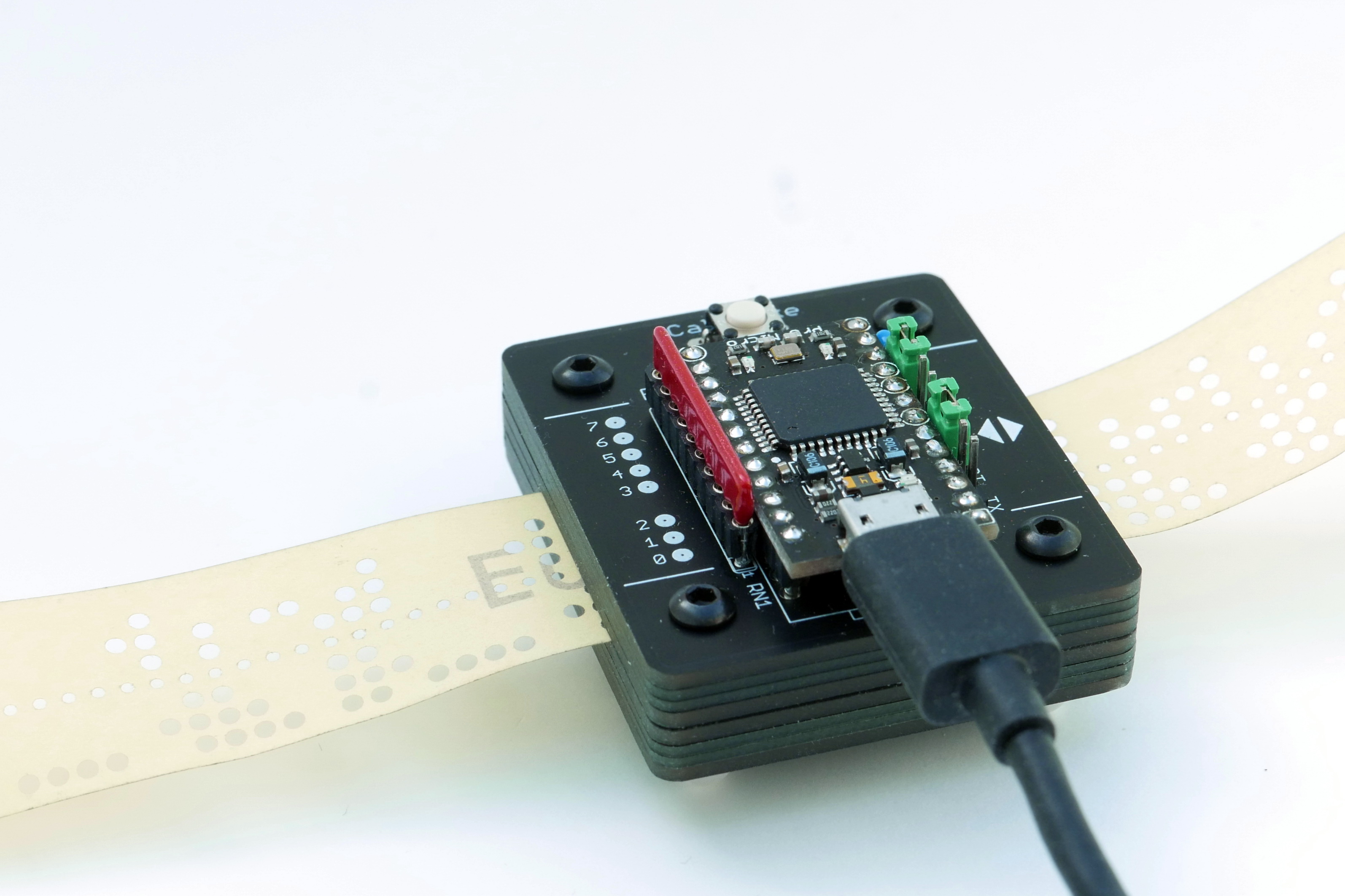
The paper tape reader is controlled by an Arduino Pro Micro. Punched holes are detected optically, via analog inputs to the Arduino and automatic thresholding in software.
Optical readers for punched paper tape have been used since the 1940s; the one developed in 1942 for the British Colossus deciphering machine was probably among the earliest. Non-motorized optical readers, where the tape is pulled through by hand, became popular with early computer amateurs in the 1970s. Oliver Audio Engineering launched the OP80A as a kit or complete unit in 1976; a replica is still commercially available today. And to this day, amateurs interested in the old paper tape format occasionally build their own optical readers.
This project takes a slightly different approach than most builds. While I also use LED & phototransistor pairs to detect the presence of holes or paper, and use the feed (sprocket) hole to trigger a read cycle, this reader does not distinguish “zero” from “one” via hardware comparators or Schmitt triggers. Instead, the on-board microcontroller (a Sparkfun/Arduino Pro Micro) reads the phototransistor currents via its analog inputs. This way it can adjust the detection thresholds in software, to compensate for tolerances between the phototransistors and to adjust to different paper materials.
Easy to use. Just connect it to any modern computer (Windows 10, Mac OS, Linux) via USB, open a terminal program or copy from the serial device to a file, pull through some paper tape, and you are in business. You can calibrate the sensors to difficult-to-read, translucent tape by pushing a button and feeding about 30 cm of test tape. But one calibration handles a wide range of paper types, and stays resident in EEPROM memory, so you don’t have to calibrate much at all.
Easy to build. Only through-hole electronic components are required. Most mechanical parts consist of pre-fabricated circuit board material – just add four screws and some adhesive tape (which is used as a spacer to guide the paper tape). No hand-selected resistor values to get the sensor switching thresholds just right, since all sensors are calibrated in software. The microcontroller is programmed via USB and the standard Arduino environment.
Works pretty well. Due to the analog sensing and software calibration, the reader handles a wide variety of tape materials robustly, including highly translucent white or yellow paper. It is insensitive to environmental light since the tape and sensors are fully encapsulated. While it’s not the fastest reader around, reading speed is probably limited by how fast you can pull the tape through without damaging it: Reading at 1.2 meter/second (500 characters per second) should not be a problem.
New Handy accessories. Several builders have designed clever accessories for the paper tape reader. Using mostly 3D-printed parts, they make tape handling more convenient. Take a look at the Accessories page!
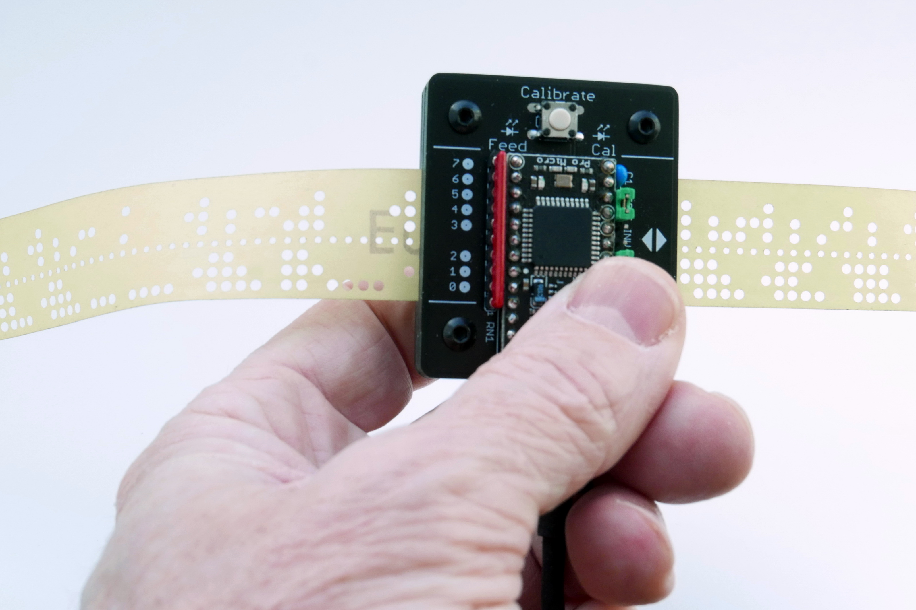
Operate the reader handheld or mounted to a base plate. Tape is pulled through manually, at up to 1 meter/second feed rate.
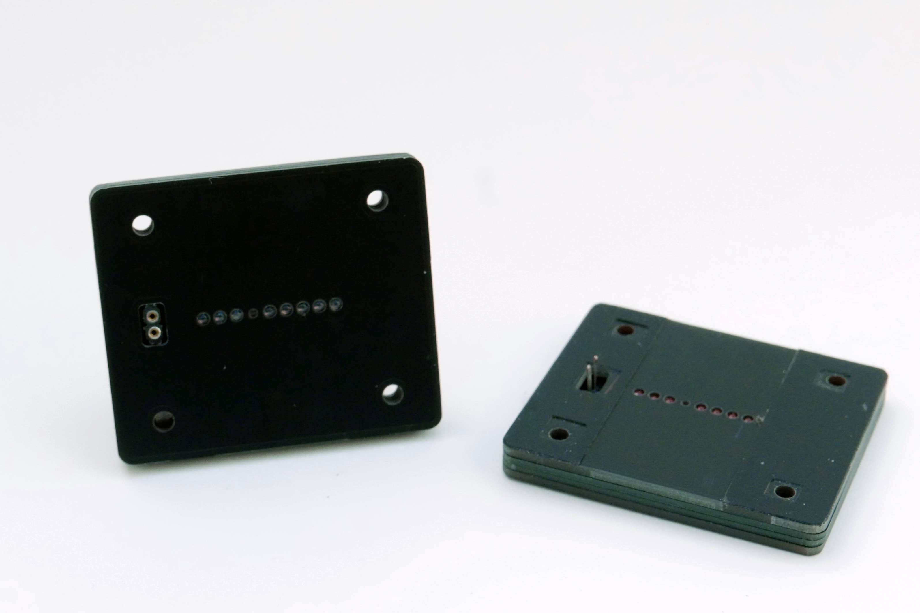
The two main modules are the phototransistor detector (left) and the LED illuminator (right). The Arduino sits on top of the detector module. Only two power connections go to the illuminator.
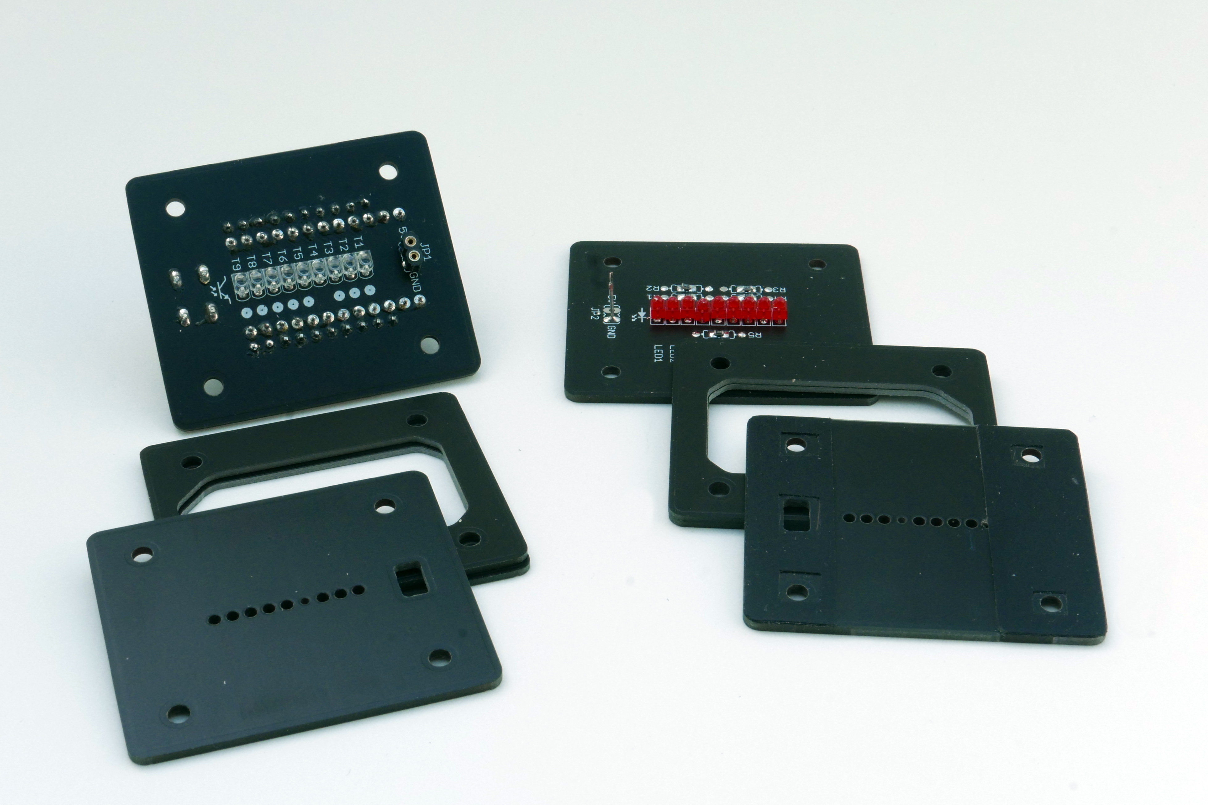
All chassis parts are made from PCB material: Circuit boards for phototransistors and LEDs, masks to precisely define the illumination and detection apertures, and light-tight spacers.