
Solving yesterday's problems today
© 1999-2023 Jürgen Müller
juergen@e-basteln.de
Solving yesterday's problems today
© 1999-2023 Jürgen Müller
juergen@e-basteln.de
This site describes my ongoing efforts to home-build a Scanning Tunneling Microscope (STM). You may take it as an illustration of the strange things people do with their spare time; but I also hope to encounter a few readers who will consider to embark on that kind of project themselves – or have even done so already, and want to help improve this site by contributing their own experiences.
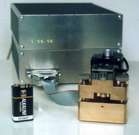
STM head in front of its control electronics and power supply
If you found your way over here, you probably know what an STM is, but I can’t resist to explain anyway: A scanning tunneling microscope is a device for imaging surfaces at very high magnifications – down to the scale of individual atoms. The STM does this by mechanically scanning a pointed tip over the surface. Piezo-electric elements can provide the necessary small translations of the tip. The trick is to tightly control the distance between tip and sample, in order to obtain a height profile of the sample. This is done by measuring the “tunneling current” between tip and sample: When the tip is brought very close to the (conducting) sample, and a bias voltage is applied between the two, electrons can “tunnel” across the isolating tip-sample gap. The rate of tunneling electrons depends sharply (exponentially) on the tip-sample distance; hence if the tunneling current is kept constant by a suitable feedback loop, the tip will track the sample surface closely. The STM image, which is acquired by recording the tip height while scanning the sample surface line by line, is actually a combination of mechanical profile and surface potential variations. Anyway, it can show the atomic lattice structure of many samples – as well as many other features on atomic or somewhat larger scales.
If the idea idea of building a toy that can image individual atoms does not appeal to you, you will probably not find this site too exciting. I loved the idea of having such a device on my desk (or rather, suspended above the desk) ever since I learnt that STMs could be built with standard electronic components and without excessively complex approach and vibration damping systems, which was in 1990. (The first STMs I had seen published, a while before Binnig and Rohrer got the Nobel prize for their invention, used a tricky piezo-stepping device, intricate glass-rod frames, eddy-current damping, and did definitely convey the message “don’t try this at home!"). However, I never got further than reading some papers in the Review of Scientific Instruments and buying a piezo tube, which I later gave away.
In late 1997, I stumbled across Jim Rice’s famous Homebrew STM page, and I decided to revive my old project. Since then, I have worked on designing and building an STM – in my scarce spare time, and with large gaps without any activity. Still, it was a lot of work, admittedly more than I expected. Without specific experience in the field, I often found it difficult and time-consuming to make design choices. A lot of technical papers on STMs have been published, many of them including drawings of the mechanics and even giving circuit diagrams, but I hardly found anything aiming for the same trade-off between price and performance I had in mind. Specifically, I did not find any well-documented amateur projects that have actually approached completion (see References).
Since I still think that building an STM makes an excellent amateur project, and I still believe that my approach might finally result in a working microscope, I decided to write up a description of what I have in mind, and what I have so far. The idea is to attract some comments, and hopefully some other amateurs who have been working on an STM design, or will consider to do so after reading these pages. Ideally, we might combine our experiences to arrive at a set of tried-and-true homebrew STM building instructions, which would lower the hurdle for others. Please be aware that currently the site is far from that – like my STM, it’s a work in progress, and far from complete.
I’m a physicist, with a background in opto-electronic instrumentation, but do not have any professional experience in scanning probe microscopy. This implies that (a) you could do it too!, and (b) I may be describing some major blunders in these pages – you have been cautioned… I would appreciate any comments from co-amateurs or experts, and would be especially happy if these pages motivate you to consider building your own STM!
Here’s a short outline of my current design. It’s pretty conventional, since I figured there’s still enough that can go wrong without exotic high-voltage circuits or finicky slip-stick approach mechanisms.
Let’s face it – it has been more than 6 years since I started this project. After two years of on-and-off activity, which accounted for most of the progress made so far, things have slowed down extremely, since I only worked on the STM very sporadically. However, not too much should be missing now to obtain a working (if not perfect) STM, and I still believe that it stands a fair chance of actually being completed eventually.
The hardware is pretty much complete: On the Electronics side, power supply, piezo drivers, stepper motor controller, A/D and D/A converters and tunneling current amplifier are in place. The Mechanics of the scan head are complete, including piezo tube and stepper motor for the automated approach. A simple vibration isolation supports the STM head.
As usual, the Software is lagging behind. I have a control program running on the DSP, which can control the stepper motor, generate X/Y scans (with flexible control of scan size, speed, rotation and resolution), and which implements the digital feedback loop for the tunneling current. It’s controlled from the PC via simple RS-232 commands; currently, I just enter the commands manually via a standard terminal program. Transmission of the scanned image data to the PC has not been tried yet – the DSP code for encoding and transmitting is there, but software needs to be written to receive these data on the PC. And I’d like some reasonably friendly interface running on the PC to set parameters and look at the scan results.
So, what’s actually working so far? The STM can automatically and reliably establish tunneling current, using the stepper motor and piezo drive in combination (without crashing the tip in the process). Under ambient conditions, the feedback loop will typically keep the tip within tunneling distance from a graphite sample for 10 to 20 minutes, before thermal drift causes the piezo to be fully contracted or expanded. Scan generation and feedback loop have been tested as far as possible by observing the tunneling current and tip position via an oscilloscope (line scans). As mentioned above, image acquisition requires additional software to be written - obviously the next point on the agenda!
This site will probably tell you more about my STM project than you ever wanted to know. The main sections are:
Mechanics, Electronics and Software – providing details of the design and implementation I have in mind, as well as some practical experience gained in building the STM. General STM theory is only referred to where it’s used to discuss design choices; please see the References section for pointers to web sites and literature providing more background.
Applications – a weak point of the site so far (and the whole project, I guess). I happily admit that right now, I consider building the STM more thrilling than actually using it, so I have not figured out any applications suitable for ambient operating conditions beyond graphite and maybe gold films. Suggestions are welcome! To pad up this section, I moved the “tip preparation” topics here.
References – incomplete but annotated reference to suppliers, other web sites and some literature.
Budget – a fairly complete list of components and their costs, included for the benefit of those not easily bored by the other topics. The current total is approximately 2000 DM, or $1100 US. This includes all major STM components, HOPG graphite samples and PtIr tip wire.
Questions – this is where I ask you questions I could not figure out yet! Of course I also appreciate your comments or questions.