
Solving yesterday's problems today
© 1999-2023 Jürgen Müller
juergen@e-basteln.de
Solving yesterday's problems today
© 1999-2023 Jürgen Müller
juergen@e-basteln.de
The “real” 9-inch cathode-ray vector monitor is the key component for this project – besides the Asteroids board, of course… A Vectrex game will be the donor for the screen, but some modifications and a custom circuit board are needed to make it work well.
The Vectrex was a home gaming console launched by General Consumer Electric in 1982. As its unique feature, it came with a built-in vector monitor! While it never was a huge market success, and apparently only was sold for a year and a half, used Vectrex systems can still be found quite easily. Ebay prices for complete, working units are well north of $100; I found an incomplete one where only the monitor worked for $45 (in Germany, where they are probably less common than in the U.S.).
It is easy to connect an Asteroids board to the Vectrex monitor. The Z (brightness modulation) signal is a direct match at 0 V to 3.5 V signal level. The XY deflection signal should also match if you turn down the levels on both, the Asteroids board and the Vectrex power board.
However, the resulting image won’t look good. The Vectrex beam deflection is too slow to follow the signals coming from the Asteroids' digital vector generator. All shapes and characters will show rounded edges, gaps in the outline and other shape distortions. It is possible to bring the Vectrex display up to the required speed, but that requires some work and electronic parts. The following paragraphs describe the custom XY driver electronics that did the job for me.
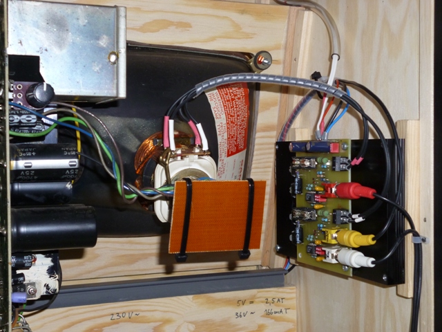
CRT mounted in plywood frame, with Vectrex power/HV board (left) and custom XY driver board (right) mounted to the cabinet side panels. Note the isolation added to the CRT neck board, to prevent accidental contact with the 170 V grid voltage present there.
In vector game forums and newsgroups, one occasionally finds the assumption that the Vectrex display is slow because the supply voltages for its deflection circuit are too low. This is plausible at first glance – when you want to change the current through an inductive load, such as the CRT yokes, the maximum slew rate is determined by the voltage you apply:
dI/dt = U/L, with current slew rate dI/dt, voltage U, and inductance L.
So the time for large-signal swings from one end of the screen to the other will indeed depend on the available voltage range. The Vectrex supply is specified at only ±9 V (although it actually was ±13 V in my system), as opposed to ±25 V or ±35 V in Atari’s vector monitors.
But the inductance of the Vectrex yokes is also significantly lower than in a Wells Gardner or ElectroHome 19" monitor: 0.45 mH for the Vectrex, vs. 1.5 to 2 mH for the big displays! This compensates for the lower drive voltage. Using a lab power supply with ±12 V for the yoke driver, my Vectrex yokes require 100 µs for a full swing. Even if the Vectrex supply were at the nominal 9 V only, the Vectrex should be able to keep up with the 120 to 150 µs full-swing time specified for the big vector CRTs. Hence: No need to upgrade to a new power supply and higher voltage XY drivers.
The real difference is in the small-signal bandwidth of the XY drivers – i.e. the ability to quickly follow small signal changes, as required when drawing characters. The Vectrex XY driver is based on an audio amplifier (LM379), and indeed appears to provide only ~20 kHz bandwidth if one looks at the dI/dt output for small dU/dt input changes. (Yes, the LM379 has a higher bandwidth when used as a voltage amplifier. But driving current through an inductive load, which shows some “inertia” to current changes, reduces the bandwidth of the voltage-to-current amplification.) In contrast, Atari’s 19" vector monitors are specified at 1 MHz small-signal bandwidth!
I estimated the bandwidth that is actually required to display Asteroids properly by using an oscilloscope (in XY mode) as my Asteroids display, and connecting it via various simple RC low-pass filters in the X and Y signal lines. This simulates the effect of limited display bandwidth. I then assessed the image quality:
20 kHz bandwidth made the image look just like it did on the unmodified Vectrex screen – not acceptable. At 50 kHz, the image became usable, but some rounding of the corners was still obvious. At 200 kHz bandwidth, the image was good – you had to look very closely to see the remaining rounding – and at 400 kHz it was perfect. So I concluded that I should aim for > 200 kHz bandwidth, and certainly did not need to shoot for 1 MHz.
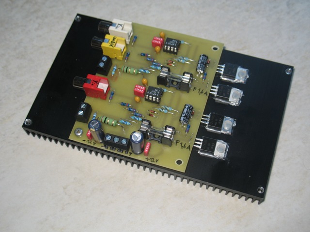
The custom XY driver board, mounted on its (oversized) heatsink. RCA connectors for XY inputs and 'unblank' output (to the spot killer circuit on the HV board). Screw terminals for XY yokes and power supply.
I ran some simulations (using TI’s free TINA-TI software), and found that this was more difficult to achieve than I had expected. Various power op-amps I tried in the simulations did not do the trick – although their specified bandwidth is way higher than 300kHz, they did not crank up the voltage fast enough to translate small input changes into output current steps through the yoke. Ideally you would want the amp to apply a quick surge of the full supply voltage to force a fast, small change of the yoke current – it takes a lot of bandwidth to control that!
The simplified circuit diagram below shows what I came up with: A really fast integrated amplifier (140 MHz video driver), followed by a simple class B transistor stage to provide the required current (±1.1 A peak). This may not be the perfect solution – I am certainly no expert analog designer, and I am open to comments! But the circuit does work well for me, providing stable operation and 300 kHz measured bandwidth.
The full circuit diagram and single-sided PCB layout are available in the Files & Links section.

Circuit diagram for single channel yoke driver.
Note that component numbers and some values in this TINA-TI simulation differ from the final circuit diagram and parts list on the Files & Links page.
Just a very brief circuit description: Like in the original Vectrex and Atari circuits, the current through the yoke is sensed via a small series resistor (R720), and the voltage drop provides the feedback signal to the LT1227. The feedback circuit is slightly different from typical op-amp circuits, since the LT1227 is a current feedback amplifier. I simply followed the ‘1227 data sheet here. At its input, the voltage divider including the diode pair (R10, R11, D2, D3) slightly pre-distorts the input signal, compressing it at higher levels – this counteracts an image distortion which the CRT creates at high deflection angles. Note that in the final circuit, the only difference between X and Y channels is in this area: Since the screen is wider in X, a stronger compression is needed to prevent image distortion, and hence resistor R10 has a lower value than for the Y channel.
The dual circuit for X and Y deflection comfortably fits on a single-sided 100*80 mm² PCB. The transistors do need a decent heatsink – although mine is sized rather generously because I still had it on the shelf. Don’t forget the mica sheets to electrically isolate the transistors from the heatsink!
The LT1227 can handle up to ±15 V supply voltages. I simply took the supply from the Vectrex power board (which I retained for the HV supply and beam control). The following section describes the minor modifications required on the Vectrex board.
The Vectrex board requires some minor changes. I left the LM379 driver in place (and powered), because it is buried beneath its large heatsink. I just disabled its inputs and outputs – that way it should hardly consume any power. Please refer to the Vectrex manual (see the Files & Links page) for schematics and a component placement diagram illustrating the following steps. I have also provided a marked-up schematic on the Files & Links page which highlights all changes:
I am not a believer in preventive “re-capping”, and have left all the original electrolytic capacitors (and other components) in place. I’ll just wait until they come back to haunt me…
So, what image quality does the customized Vectrex monitor provide in practice? Certainly enough to please me! The lines are crisp and corners are very precise. The beam intensity is nicely modulated, showing asteroids in different “colors”, the brighter score for the active player, bright saucers and beautifully glowing shots.

Look Ma, no pixels! The CRT was hard to focus and photograph properly, so this picture does not do it full justice. I am quite pleased with the image quality: crisp lines, precise corners, and very nice intensity dynamics for the saucers and shots.
Is the image perfect? Not quite. There is a very slight wobble in the X direction – much less than what I saw on my oscilloscope in earlier test jigs. I wonder whether this is an interference between our 50Hz line frequency and the Asteroids image frame rate, which seems to be 60Hz. But since the effect is so minor that I don’t notice it at all during gameplay, I have not been motivated to track it down yet. There also is minor pumping of the image depending on the amount of bright objects on the screen; most noticeable when the flashing “Push Start” is displayed in attract mode. This is most likely due to the not-so-beefy HV transformer in the Vectrex. Once again, I don’t mind this minor effect – fortunately, since there is probably no easy fix for it…
Finally, there is an effect which I did find intriguing – shown in the image below. Some lines are a bit short, visible e.g. in the letters Y, R, I and H. Using an oscilloscope I found that (a) the effect is also there when using the scope as an XY display, and (b) looking at the temporal sequence of drawing, it appears that lines end early (rather than start late). I don’t suspect my scope to introduce any delay in the XYZ signals – it is a modest 20 MHz scope, but still much faster than the Atari monitors at 1 MHz. So the “short lines” seem to be an effect created by the Asteroids board itself. My conclusion is that the Asteroids vector generator actually switches lines off slightly early, to compensate for a delay introduced by the original 19" vector monitors. I wonder whether this is a known behavior? Comments are appreciated!
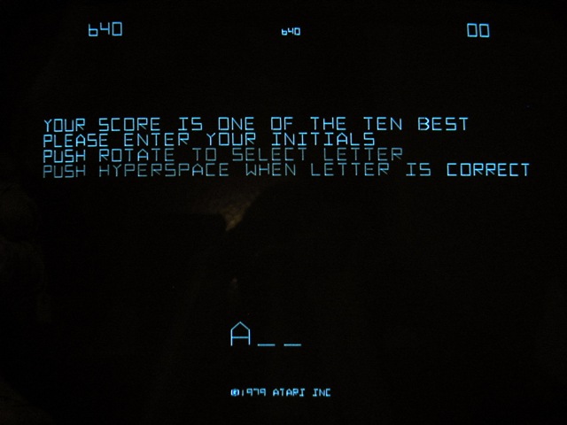
The Vectrex Z beam intensity (Z) modulation actually seems too fast for Asteroids! Note the slight asymmetries in the letters 'H' and 'I', and the short diagonals in 'Y' and 'R'; discussed in the text above. The apparent brightness differences in the letters are an artefact of the photograph.
When working on the monitor, you are not only exposed to mains voltage, but also to high voltages generated within the monitor’s circuit: 170V grid voltage on the power board and CRT neck board, and 6kV acceleration voltage at the HV transformer and CRT anode. Be sure to keep yourself safe during the build process, and to build a system that is safe to use! I will not provide any specific safety instructions here – if you are not confident that you have the adequate technical background, please seek assistance from somebody with the required expertise!