
Solving yesterday's problems today
© 1999-2023 Jürgen Müller
juergen@e-basteln.de
Solving yesterday's problems today
© 1999-2023 Jürgen Müller
juergen@e-basteln.de
Since the cabinet was built from scratch, I also had to provide the electrical infrastructure to get the Asteroids board going – power supplies, audio amplifier, and marquee illumination.
All power supplies are mounted on a vertical board in the lower front part of the cabinet.
The Vectrex brings its own transformer. When removing it from the Vectrex cabinet, be sure to label the input and output wires. The input can apparently be configured for 115, 220 and 240 V and is wired appropriately on a small circuit board which also holds the primary fuse. I discarded this circuit board and replaced it with a proper fuse holder (with a 250 mA slow-blow fuse for operation at 230 V). Before disconnecting it from the transformer, have a close look at the wiring of the transformer’s input on this little board; the connection and wire colors are not documented in the official Vectrex schematics!
The Asteroids PCB needs approx. 2A of 5V DC to supply most of the digital circuitry. A small switching power supply will do the job. I used a MeanWell RS-25-5, rated at 5A, with a 2.5 A fuse in the low-voltage output.
Please note that the 36V AC supply shown in the Asteroids circuit diagrams is actually 2*18V! You will need a transformer with a center tap, and connect that tap to the Asteroids GND level. A transformer with 6W output rating will be sufficient. I placed 0.16A fuses in the low-voltage output, and a 63mA fuse on the primary side (for 230V operation).
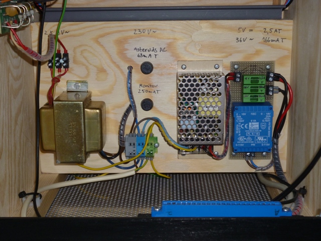
Left to right: Power supplies for Vectrex monitor, Asteroids +5V DC, Asteroids 36V AC.
The Asteroids board edge connector (with 2*22 pins) is an outdated one, but still available from various suppliers specializing in arcade game parts. It is often called a “Molex” connector – but be aware that Molex makes other, incompatible types of edge connectors as well.
The quality of the connectors I got was not great. The plastic melts easily when soldering to the contacts, allowing the contact pads to shift. Be sure to solder swiftly and don’t apply strain to the contacts while soldering. The metal of the solder tabs is also quite thin, so they bend easily once soldered to heavy-gauge wire. Applying heat-shrink tubing around each connection is recommended!
Worn or burnt-out edge contacts appear to be relatively common on the Asteroids game board. A thin layer of solder can be applied to contacts which show wear but are still mostly complete. To limit the current across the +5V and GND contacts, use all available 4 contacts for each of them. Pins 21 and 22 were originally used to sense the voltage on-board to allow the power supply to compensate for voltage drops along the supply wiring and contacts. Not needed with proper wiring, and not supported by most simple power supplies anyway, so these can also used as supply pins:
Don’t use the audio amplifier on the Vectrex power board! It adds a lot of buzzing noise, since it lives in the noisy environment of the CRT driver. Also, the individual AUDIO1 and AUDIO2 outputs from the Asteroids board carry a lot of noise – but most of that will cancel out when both AUDIO signals are fed to an amplifier with differential inputs. The LM386 amplifier in the Vectrex is set up in a single-input configuration only – another reason for not using it.
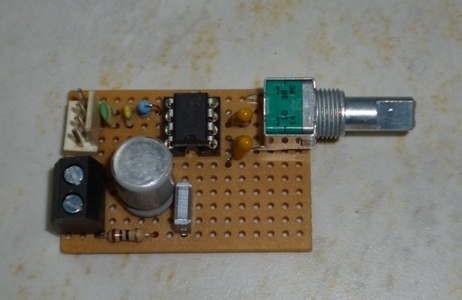
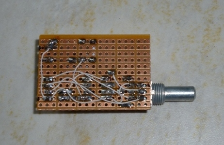
A differential amplifier based on the LM386 is just as simple as a single-input one. You will need a stereo potentiometer, however, since the audio level needs to be regulated on the input side of the LM386, for each of the AUDIO 1/2 signals. I simply hand-wired the circuit on perfboard and mounted it to the cabinet’s back panel via the potentiometer.
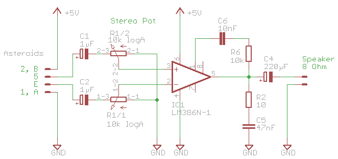
Small LM386 audio amplifier. Differential inputs, using the AUDIO1 and AUDIO2 outputs from Asteroids, help to reduce the buzzing noise.
LEDs work well for back-illuminating the marquee. White LED strips are available from electronics suppliers, DIY stores etc.. Mine is actually from IKEA – one third of their “LEDBERG” strip. One segment is just the right length, and consumes only 50 mA at 12 V. I connected it to the 13.6 V DC supply from the Vectrex, via a 27 Ohm resistor to drop the excess voltage.
These LEDs emit light over a rather wide angle. A distance of only 7 cm from the translucent marquee image is sufficient to provide a nice and even illumination, which does not show the individual LED spots anymore.
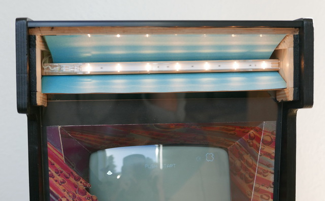
A white LED strip illuminates the marquee. A shield below the LEDs stops stray light from entering the monitor bezel. The blue cardboard reflector helps to compensate for the slightly 'warm' light color of the IKEA LED strip.
You will be working with mains power when building this, and with even higher voltages (up to 6 kV) when dealing with the CRT display. This implies risks of fire and electric shock. Be sure to keep yourself safe during the build process, and to build a system that is safe to use! I will not provide any specific safety instructions here – if you are not confident that you have the adequate technical background, please seek assistance from somebody with the required expertise!