
Solving yesterday's problems today
© 1999-2023 Jürgen Müller
juergen@e-basteln.de
Solving yesterday's problems today
© 1999-2023 Jürgen Müller
juergen@e-basteln.de
A Vectrex monitor is very close to half the size of the original monitor in the upright Asteroids cabinet (9" diagonal vs. 19"). The width of the Asteroids circuit board also happens to be quite close to half the width of the full-size Atari cabinet (29.3 cm vs. 64 cm).
Nevertheless, I did not opt for an exact half-scale replica of the Asteroids cabinet. I wanted a game that is nicely playable when placed on a table or shelf. Hence I chopped off most of the base, because otherwise the control panel would have been uncomfortably high up. Since I wanted to show the circuit board through the back of the cabinet, I needed a straight back of sufficient height. Therefore the cabinet does not have Asteroids' angled back, but has a vertical back and a slightly sloping top. The result works for me – I think that with its marquee, monitor, bezel and control panel graphics, it nicely conveys the Asteroids look and feel.
When designing the cabinet, there are a few key components that determine essential measurements:
With the major dimensions determined by the CRT and the main PCB, I found that there was enough space in the cabinet to also fit the power supplies and monitor circuit boards. Here’s what I ended up with:
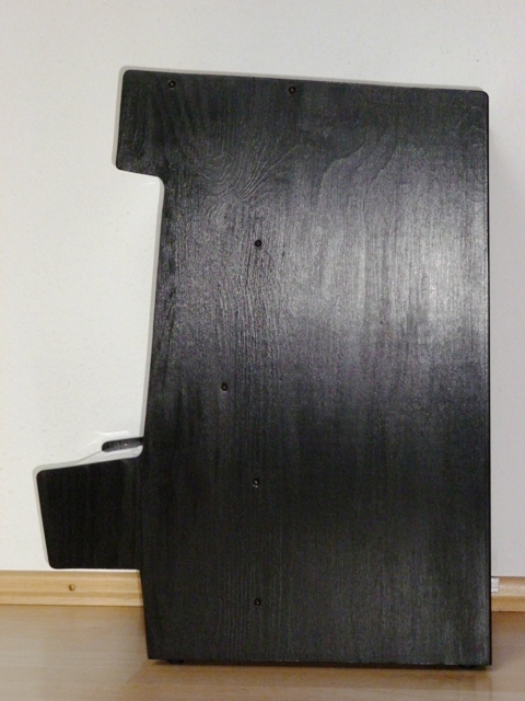
The side view shows pairs of screws where the cross panels making up the structural frame are attached: Front top cover (serves as carrying handle), monitor mounting frame, and vertical mounting board for transformers in the bottom.
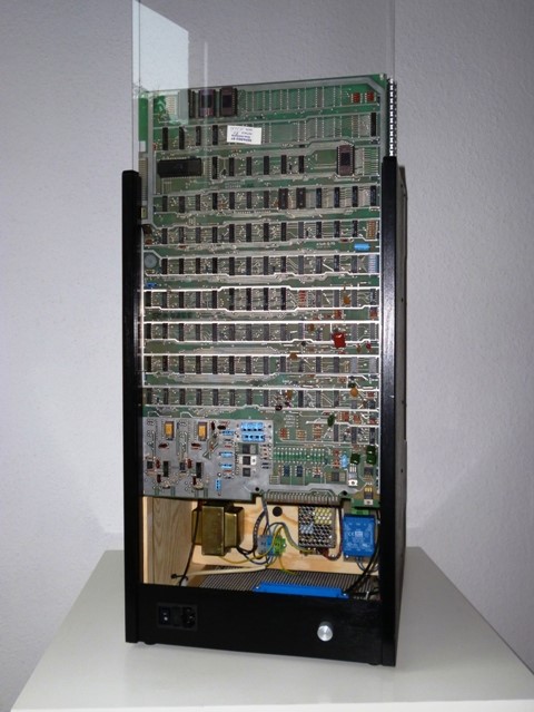
The cabinet is just as wide as the circuit board (plus the thickness of the side walls). The circuit board and Perspex back pane are guided in grooves formed by glued-on wood strips. They slide up after the perforated aluminum top cover has been removed.
The structural frame is made from 12 mm plywood boards:
The front and back are dominated by 3mm Perspex panes. That thickness is strong enough and not too heavy for
Several narrow panels of 4mm plywood complete the front and back: Bottom of marquee box and control panel, front panel below the control panel, back panel with power connector below the PCB and Perspex pane.
Top and bottom have large inserts of perforated Aluminum sheet to allow good ventilation. The system does not need a fan and won’t run hot. (Power consumption is a moderate 40 to 45 W.)
Finally, heavy paper stock (or thin, white coated cardboard) is used for the monitor bezel and the control panel graphics. (It is protected by the Perspex in both cases.) See the Files & Links section for the artwork.
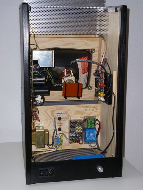
The CRT is mounted to a plywood board with an appropriate cut-out, using the original mounting tabs in the CRT corners. All power supplies are mounted to another plywood board, arranged vertically in the base of the cabinet. Monitor electronics attached to the side walls of the cabinet, with short connections to the CRT.
The structural frame parts were first screwed together (helpful for several iterations of test fits). For the final assembly, I applied wood glue to the top cover/handle and the CRT frame, but decided to also leave the screws in place for added stability. Wood strips are glued into the corners between side panels and the lid and CRT frame to reinforce the assembly. The thin plywood panels are screw-mounted where I may need future access (e.g. the marquee bottom panel, which holds the marquee front panel in place, and the lower front panel, which carries the speaker); others are glued. Wood strips support these panels too. Of the Perspex panes, only the control panel is attached with screws. The other Perspex pieces are held in place by guide rails formed by wood strips (back), plastic “L” profiles (marquee), or by the control panel and the marquee box (screen bezel).
I did not use T-molding around the edges of the side panels. The sanded plywood edges look good to me. I also left the side panels without side art, since the front and back of the cabinet are quite colorful already. Just sanded the wood and stained it black, to show the wood grain.
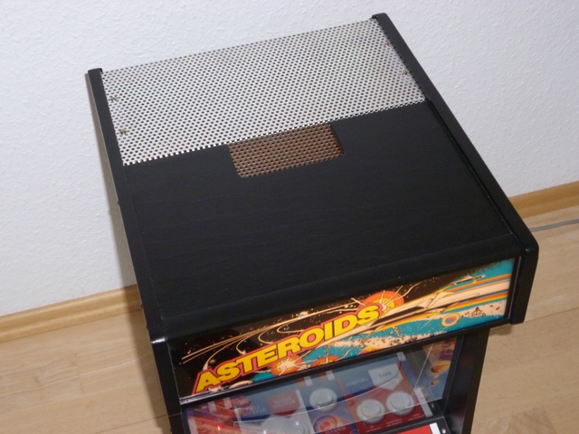
Ventilation at the top...
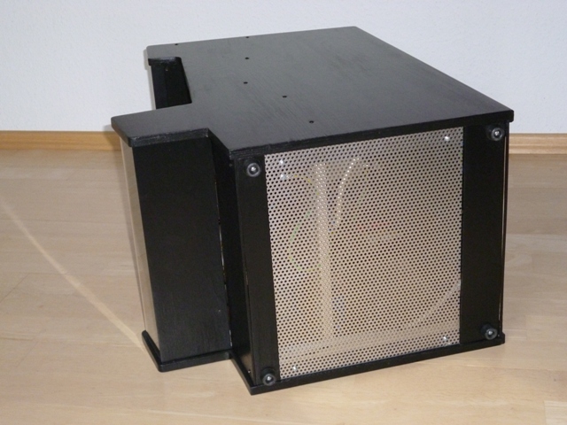
... and bottom of the cabinet. The power supply mounting board can be seen through the perforated aluminum. Both aluminum sheets are grounded for electrical safety!
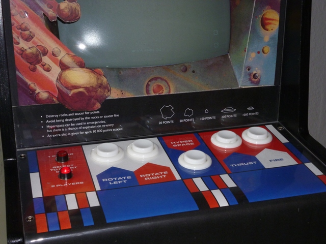
I am sure one can find suitable small buttons and arrange them in a half-scale model of the original Asteroids control panel. I decided against that – for good playability, I wanted a full-scale button layout. The original Asteroids panel has plenty of graphics and free space around the actual buttons, so there is more than enough room for the five main buttons in a half-size cabinet. The 1/2 Player pushbuttons were placed to the left of the main buttons rather than behind them, to limit the depth of the control panel (while still keeping an adequate wrist rest in front of the buttons).
Arcade-style buttons were obtained from one of the arcade parts shops, and LED-lighted pushbuttons for player selection from a regular electronics store. (I believe that replica Asteroids player 1/2 buttons and conical caps are still available, but I was too cheap for those.)
I did my own layout of the panel graphics (available in the Files & Links section), using some of the design elements from the original panel. Did not find room for the zig-zag arrows though…
The control panel material is clear Perspex, rather than the sheet metal used by Atari. That way, I could simply print the graphics on heavy-stock paper and attach them beneath the Perspex. They look nice and glossy and are well-protected. The front part of the Perspex sheet is bent down, with a smoothly rounded edge that is easy on the wrists.
Perspex sheets can be bent under hot air from a heat gun (for stripping paint etc.). Find a suitable mold – a kitchen counter with a suitably rounded edge worked for me. Adjust the Perspex over the edge, hold it in place with a flat board and clamps. Gently heat the area where you want the bend – keep the heat gun moving to avoid local overheating. With the other hand, push down gently on the part you want to bend down. When the Perspex softens, keep applying heat and pushing down. Once the desired angle is reached, remove the heat but keep holding the Perspex in place – it may want to straighten a bit while cooling.
Perspex can be sawn, sanded and drilled, if you cool with a squirt of water when using power tools. (Without cooling the Perspex may melt and create a mess – most effective when it clings to a large drill and tears apart the whole work piece…) Drilling with a conical hole cutter, intended for creating large holes in sheet metal, has worked great for me. It gradually shaves material away from the rim of the hole. Even for small holes, starting at about 6 mm diameter, this has produced cleaner results than conventional drills.
I opted for full-size buttons and a full-size button layout. 1 or 2 Player buttons are placed on the side to limit the depth of the panel.
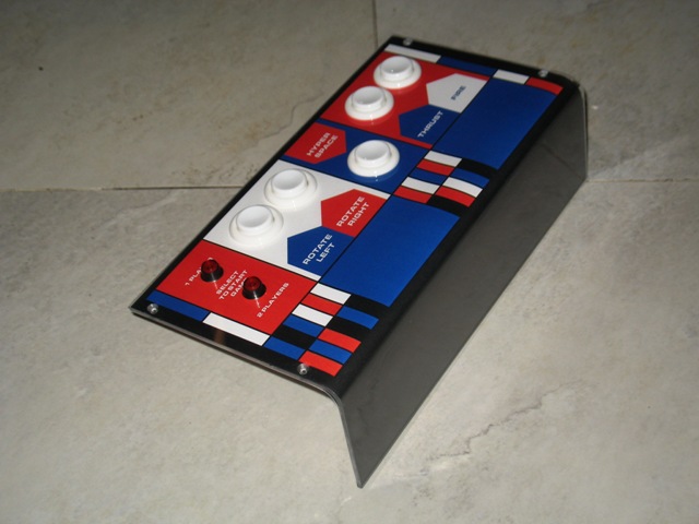
The panel is made from a piece of 3mm Perspex bent under hot air from a heat gun.
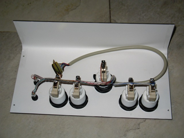
The control panel graphics are printed on heavy paper stock. Held in place underneath the Perspex by the buttons and by adhesive strips along the Perspex's edge.
Scans of the original Asteroids marquee motif and of the monitor’s cardboard bezel are freely available on the internet; please see the Files & Links section.
I simply printed the marquee on a color inkjet printer – the main challenge was to find printable transparent film these days. The film is placed behind a 3mm Perspex sheet, and backed with a piece of translucent paper as a diffuser. This sandwich is held in place by black “L” profiles running along the top and bottom edge of the marquee box. The marquee motif is back-iulluminated by a strip of white LEDs; some more details at the bottom of the Electrical section.
The monitor bezel was printed on heavy paper stock at 48% scale. For flatness and mechanical stability, it is glued onto a 4mm plywood sheet with the appropriate trapezoidal cutout. In the original Asteroids cabinet, the black frame around the bezel is apparently printed or glued to the back of the Perspex cover pane. I simply glued it onto the plywood as well (using plain black paper on the top and sides, and home-printed instructions at the bottom), so the Perspex remains plain. As an added benefit, the big asteroid on the front cardboard decoration actually jumps out over the black frame – that must be what the graphics designer intended, but apparently it was always hidden behind the black frame in Atari’s cabinet ;-)